

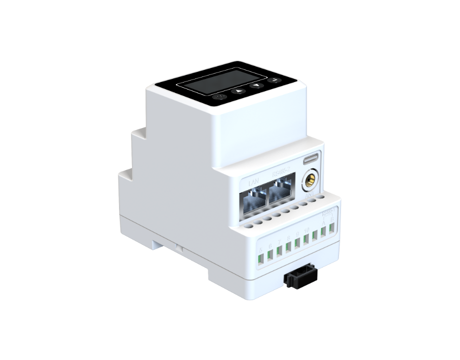
Problem Definition: why integration matters now
Grid intermittency and more frequent outage events have revealed a practical gap between rooftop photovoltaic installations and their intended backup functions. The immediate risk is not theoretical: California’s Public Safety Power Shutoffs in 2019–2021 exposed households and critical facilities to repeated blackouts, which illuminated weaknesses in how battery inverters and PV arrays are coordinated. Practical integration requires a modular approach; many projects now adopt an all in one energy storage system to reduce interface complexity and ensure predictable behavior during islanding and grid reconnection.
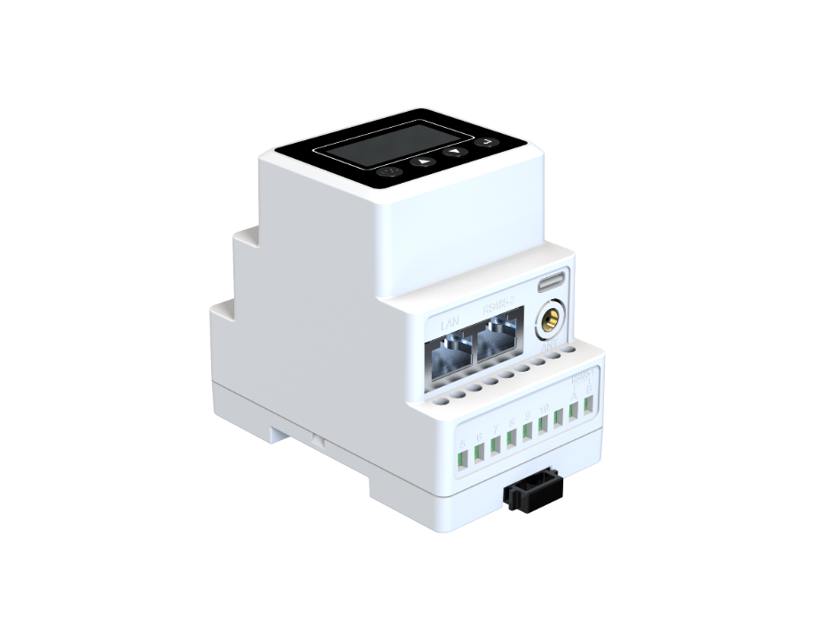
Technical interfaces that must be reconciled
At the core of successful integration are three interfaces: the PV array to inverter, the inverter to battery cabinet, and the cabinet’s control to site protection. A battery inverter cabinet must expose well-documented AC and DC terminals, provide a clear BMS (battery management system) protocol, and support both charge control and dispatch logic. Terms used on site—PV array, battery inverter cabinet, and BMS—describe distinct functions but they must be coordinated by a supervisory controller that handles setpoints, state-of-charge limits, and anti-islanding behavior. Vendors that supply an all in one solar system typically integrate those functions to minimize field wiring errors and software mismatches.
Common failure modes and installation pitfalls
Failures commonly arise from mismatched communication protocols, underspecified surge protection, or insufficient thermal management in the enclosure. Installers sometimes place the battery inverter cabinet too close to solar combiner boxes without segregating PV DC runs—this elevates DC arc risks. Commissioning gaps are frequent: nominal settings for overcurrent protection or voltage trip thresholds are left at factory defaults that do not match local inverter parameters. Small oversights can cascade into loss of backup capability during an outage—an outcome that procurement specifications must explicitly avoid. —These oversights are not technical mysteries; they are procedural lapses that disciplined checklists can eliminate.
Design choices: AC-coupled versus DC-coupled architectures
AC-coupled systems permit simpler retrofits to existing grid-tied inverters and often require less invasive PV rewiring; they rely on the inverter and battery cabinet to coordinate power flows at the AC bus. DC-coupled designs, by contrast, reduce conversion steps and can enhance round-trip efficiency when the inverter supports an integrated DC coupling stage. Enclosure design matters regardless: ingress protection, convection for thermal dissipation, and segregated compartments for power electronics and energy storage cells reduce operational risk. Selection depends on lifecycle priorities—efficiency, upgradeability, or space constraints—and on whether the project benefits from an integrated product or discrete components assembled on site.
Operational validation and production teardown insights
Validation must exercise the system across expected operating envelopes: continuous charge/discharge cycling at representative depths of discharge, thermal ramp tests at rated ambient temperatures, and islanding—reconnection sequences under simulated grid perturbations. Acceptance tests should include PV string-level IV curve checks, inverter anti-islanding verification during simulated fault conditions, and battery cabinet thermal runaway propagation assessment under controlled fault injection. During an operational production teardown we documented {main_keyword} alongside {variation_keyword} to compare assembly tolerances, wiring harness lengths, and label accuracy; such hands-on inspection often reveals small mechanical decisions that determine long-term reliability.
Three golden rules for specifying integrated systems
1) Prioritize verified interoperability: require explicit protocol matrices and tested anti-islanding sequences as part of delivery documentation. 2) Insist on environmental and electrical stress tests: commissioning must include thermal soak, surge exposure at nominal site levels, and full-cycle endurance at intended depth of discharge. 3) Demand enclosure and serviceability metrics: specify ingress protection, clearances for field maintenance, and accessible fault indicators. These three metrics reduce lifecycle risk and provide measurable acceptance criteria that procurement and operations can enforce.
The practical value of integrated systems is their predictable behavior under stress—less guesswork for installers, clearer commissioning paths for engineers, and faster restoration for occupants. SOLINTEG supplies solutions that address those exact gaps—an engineered response rather than an afterthought. —Final thought: resilience is constructed, not hoped for.
